
XCOMPUTE is an Integrated Engineering Environment (IEE) — a carefully-designed stack where research is organized by technology taxonomy. This page outlines our forward-looking R&D and the trajectory of the platform.
Background
Prototype FDM LES simulations from Space Energetics LLC kicked off R&D in 2011-2014. That family of 2D Matlab CFD and E&M codes is considered the "X1" prototype. "X2" then applied the C++11 spec and evolved through requirement capture and engineering process. In 2020, C++20 was standardized and the foundations of XC and XCOMPUTE technologies were defined. It took three small teams a decade to reach the premiere public release in Feb 2026.
IEE Taxonomy
We organize research around four interaction modes, which informs our technology stack:
server host
(operational)
terminal utility
(in development)
edge peripheral
(in development)
client interface
(operational)
Infrastructure
XC apps bind to languages via our XC-Messages Protocol Buffer definitions.
Foundational maths, RPC, cryptography, and serialization live in the XC-Common module.
Candidates are compiled to target architectures, initially focused on x86_64 and ARM64.
Applied AIML
Secure onsite inference is available to teammates for XC code debugging and dev.
Open models are used as foundations for specialized training against proprietary XC code.
Initial internal services are deployed in 2026; additional core services are planned.
Heterogeneous Data
Patented data tech enables optimal vectorization and handling for CPU and GPU processing.
US11373019B2 covers a key differentiator for industrial customers, yielding maximum storage density and parallel computing performance at scale.
View Patent →Implicit+Explicit Geometry
Dynamic shape definition, dynamic parallel octrees, and SDF-based contacts. These form the foundation of our emerging advanced solvers.
Explicit geometry construct from discrete polyhedra (rendered as points, lines, and triangles)
Implicit geometry construct from (SDF) field functions and operators (rendered as continuous shapes)
Geometry Slides →Geometry Paper →
Systems-of-Systems
Declarative "noun" unit, instanced; defines the composition of objects by users.
Ongoing R&D: abstract and multi-fidelity modeling and coupling, multi-objective optimization, server-server distribution.
Server Source Code →Algorithms-of-Algorithms
Procedural "verb" unit, singular; operates on objects defining behavior.
Ongoing R&D: complex and relativistic physics, state reactions, and high-order and dynamic sampling.
Architecture Slides →Architecture Paper →
Rendering
Rasterization renders explicit geometries, while ray-marching renders implicit geometries.
Explicit integration tests demonstrate late-stage raster:
Explicit render with geometry.glsl →Implicit integration tests demonstrate 2D painting and 3D shape ray-marching:
Implicit render with fragment.glsl →Extensions
The client interface already enables file management across sessions; it is possible for users to call other tools and scripts.
An array of further levels of integration are under study.
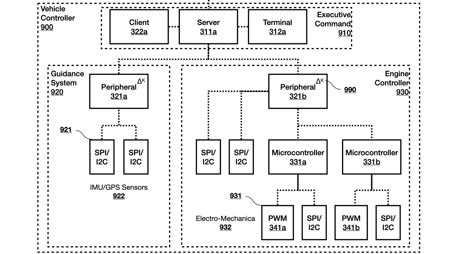
MPU Peripheral
With xcompute-edge, any 64-bit linux OS with 4+ cores becomes a 1 Gb/s data+command funnel.
The MPU encodes/decodes commands/data between xcompute-server and popular DAQ and custom PiXC microcontrollers.
Source Code →MCU RTOS
A bare-metal hard-RTOS for dual-core 32-bit microcontrollers performs timing-critical low-level operations such as PWM, GPIO, and SPI. Open and customizable code.
Sensor Fusion
Abstractions for peripheral devices and high-level sensor/effector fusion. The CPU-MPU-MCU funnel architecture maps server-host systems onto hardware.
Terminal Utility
The command-line interface for interacting with the server host. Designed for engineers who need to run batch jobs, inspect results, and manage the platform without a GUI.
Source Code →